Thermostat reset circuit
DS1821 Reset Circuit by Doug Collinge
Introduction
The Dallas DS1821 "Programmable Digital Thermostat and Thermometer" is a member of the "1 Wire" family of interface chips but has a number of peculiarities not shared by the others. The DS1821 has no address, which means that only one DS1821 can be on a given bus. The three-pin DS1821 uses the same pin for both the 1-wire bus input/output and for the thermostat temperature high/low output. The DS1821 can therefore either be a 1-wire slave or a thermostat at any given time but not both.
When the DS1821 comes from the factory it is configured to be a 1-wire slave so that the internal registers, temperature, and so on can be accessed and programmed. Once the desired parameters have been written into the DS1821 the "thermostat mode" bit is set and the device removed from the bus. When power is applied again the circuit comes up as a thermostat, driving the output pin high or low according to the temperature and the setting or the "polarity" bit. For further details consult the DS1821 datasheet.
Once the DS1821 comes up as a thermostat it will not return to 1-wire mode until it receives a special signal sequence, as follows:
+5V is removed from the power pin while holding the data pin at +5V.
The data pin is pulsed to 0V for 1us, then back to +5V for another 1 us.
Step 2 is repeated 15 more times for a total of 16 low-going pulses.
+5V is restored to the power pin.
Each pulse is nominally 1 us wide and separated by 1us of +5V but there is a good deal of latitude in the timing. The precise timing constraints are specified in the datasheet.
This circuit generates this timing using cheap and easy-to-get parts. No precision components are required and there are no special construction requirements. It would have been possible to design a much smaller circuit using a microcontroller but that would require special software or hardware to program. This circuit can be built with only a soldering iron or on a prototyping plugboard.
Circuit Operation
The reset signal is generated by pushing a momentary contact switch, S1. Closing S1 shorts capacitor C2 to ground, generating a fast rising edge at the output of the schmitt trigger gate U1D, from which the rest of the sequence is timed. When S1 is released C2 recharges to +5V via R2. The falling edge is ignored by this circuit.
The "power off" interval is timed by an RC 1-shot consisting of C3 and R3. The time-constant was chosen to make sure that the power off interval lasts sufficiently longer than the 16 pulses discussed below. The slow edges of the 1-shot signal are cleaned up by the schmitt trigger gate U1C, which drives the DS1821 power pin directly. The 74HC132 is a CMOS device and was chosen for its ability to drive its output to near the voltage on its power supply pin.
Another RC 1-shot with a shorter time-constant (C4, R4) generates a short positive-going pulse that is used to reset a counter, U2. U2 is actually two 4-bit counters but they are cascaded here into a single 8-bit counter. Once the counters are reset the Qn outputs all go low. The sixth bit (pin 10) is inverted by U1A and used to gate the timing oscillator, U1B.
The timing oscillator is a standard schmitt-trigger relaxation oscillator. If the output is high, capacitor C5 is charged through R5 until its voltage reaches the upper threshhold on pin 5. Then the output goes low and the capacitor discharges back through R5 until ithe voltages reaches the lower threshhold and the output goes back high. This repeats indefinitely and the time-constant is chosen to give a frequency of about 2 MHz. Precision is not required since the specifications of the DS1821 allow anywhere from 200 khz to 20 MHz.
This oscillator is implemented with a NAND gate so it can by turned off and on by a signal on U1B, pin 4. Low turns it off; high turns it on. The gate signal is inverted by gate U1A from bit 5 of the counter, which goes high when the counter is reset. Therefore the oscillator begins to run as soon as the counters are reset and continues to run until the count has reached 32. When the count has reached 32, bit 5 (U2, pin 10) goes high, which turns off the oscillator. This state is stable until the counter is reset again. The seventh and eighth bits are not used and stay low at all times.
The bit 0 output of the counter (U2, pin 3) generates 16 high-going pulses during the course of this sequence. These pulses are coupled to the output transistor Q1 via a capacitor to avoid saturation, which would make the 2n3904 too slow. The collector of Q1 is connected directly to the data line of the 1 Wire bus and generates the necessary pulses to reset the DS1821.
Software
I am using the excellent owfs software for Linux, which is GPL licensed and available for free on the web. It has interface code for all the 1-wire chips, including the DS1821. In fact, I wrote some of that DS1821 interface code.
If you are not using Linux I don't know what you do.
How to Use the Circuit
Connect the 1-wire bus to a computer using some kind of interface. I'm using a DS9490R USB interface.
Connect the reset circuit onto the bus. Push the button to clear any random state the counter may have acquired during power-up.
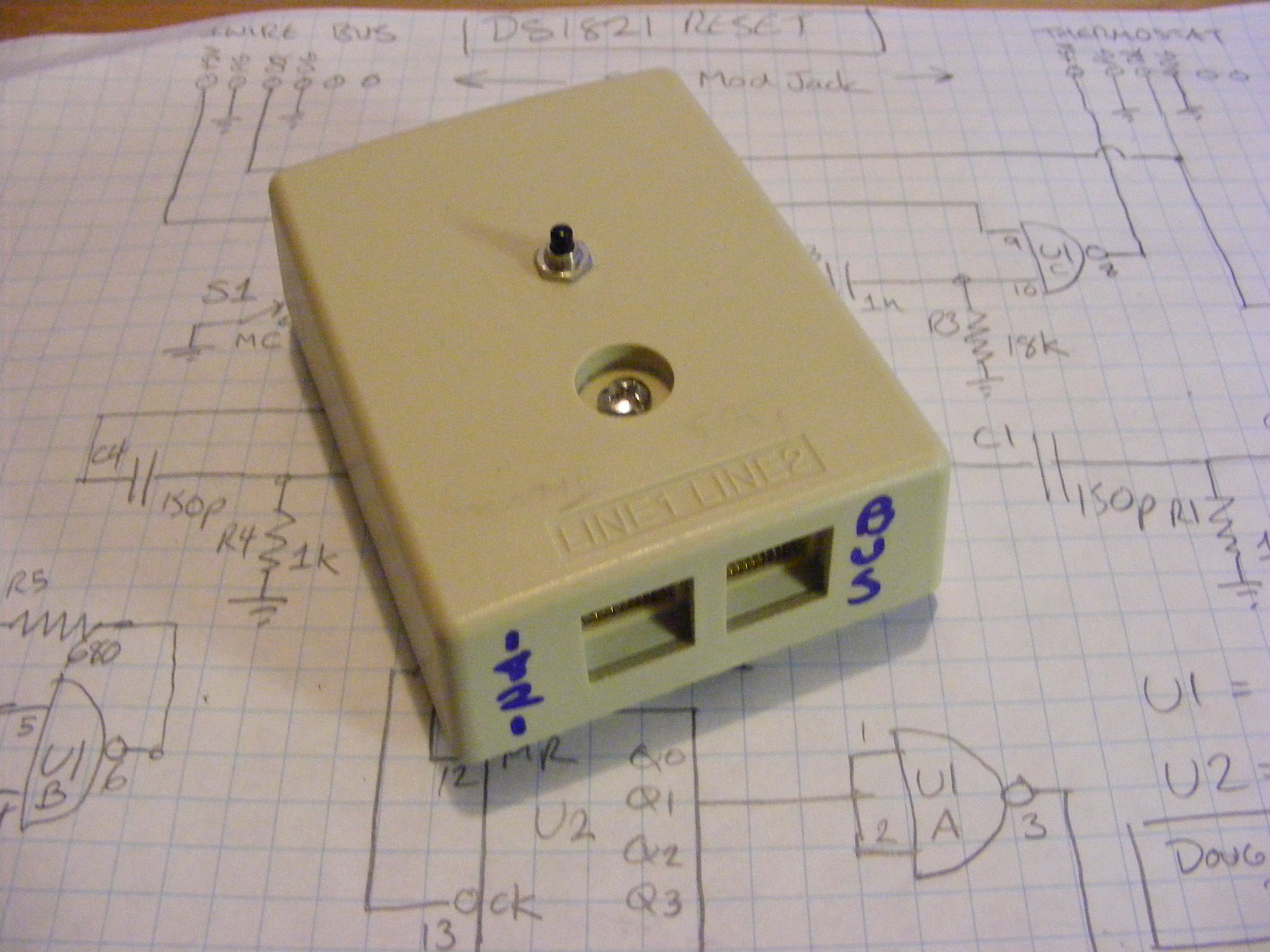
Plug the DS1821 into the reset circuit. I'm using 6-pin mod jacks and have my DS1821s attached to 6-pin mod plugs.
If the DS1821 is already in 1-wire mode you will be able to read the temperature and other internal registers. If not, you may get data errors as the DS1821, thinking that it is a thermostat, drives the bus with its thermostat output. Push the button on the reset circuit and the DS1821 will go into 1-wire mode so you can alter the internal configurations. It is not necessary to change the thermostat mode bit on the DS1821 if all you want to do is change the temperature settings or other parameters because it will stay in 1-wire mode until the power is cycled and then come back up as a thermostat.
Credits
Circuit designed and built by Doug Collinge in 2007. Thanks to David Harris for the loan of his scope and to Paul Alfille and his collaborators for owfs.
Schematic

Timing Diagram

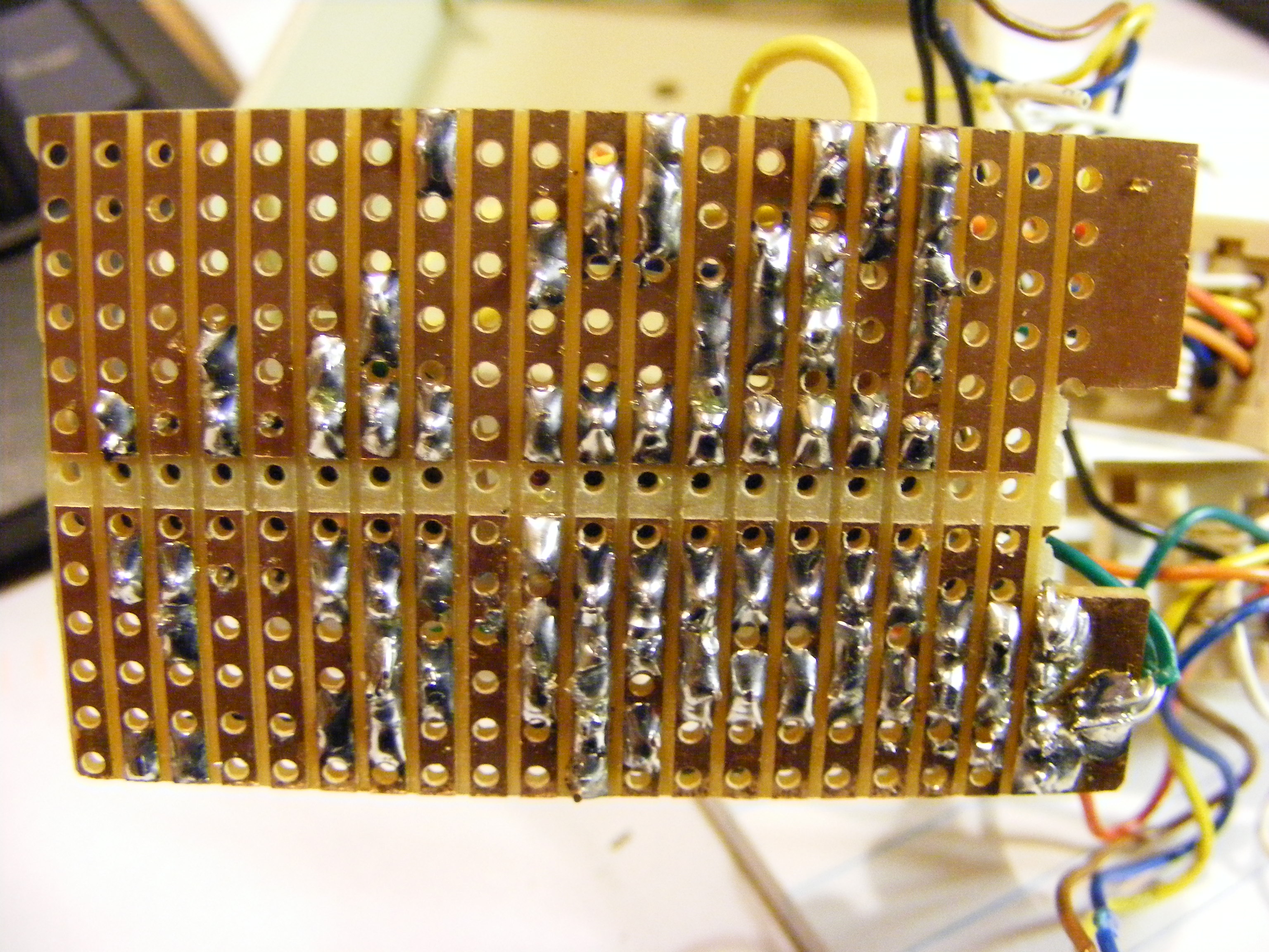
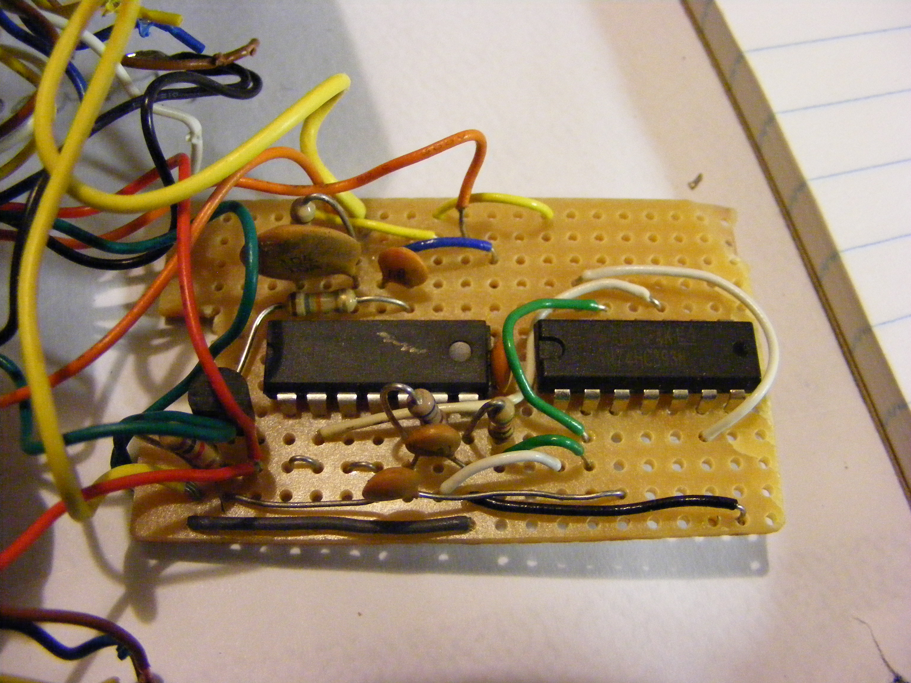
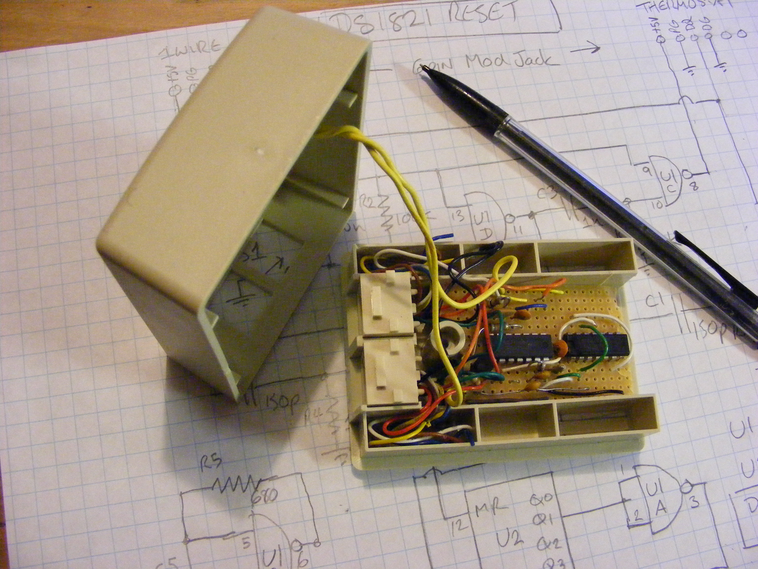
Photos
Previous page: Hack-A-Day
Next page: Custom hardware